Table of Contents
Flashing CC2531 stick with NodeMCU
Introduction
Smart home and building, is a concept of adopting a large variety of Internet of Things (IoT) to aid control and automate electronic devices in home or building. For example to control handwasher/dryers or catch some information from your refrigerators, to active lighting, heating and cooling systems, or more often entry sensors or alarms for the security systems. The goal of it is to enable more intelligent resources and processes, which expand the building’s capacity to operate in a more efficient, flexible, interactive and sustainable way. This concept is not new, but it has evolved mainly due to the development of new technologies and a variety of communication protocols. In particular, ZigBee and Z-Wave are typically characterized as protocols with low power consumption, low data communicationrate.
That tutorial is part of the series of articles about IoT and now it will be focus on the Zigbee protocol.
ZigBee (IEEE 802.15.4) is pretty nice technologie but range is limited due to the fact that it shares the same 2.4GHz band as WiFi and many other modern devices. Especially if you have a larger apartment, house or garden, you probably want to extend the range of your smart home gateway.
Interface Device
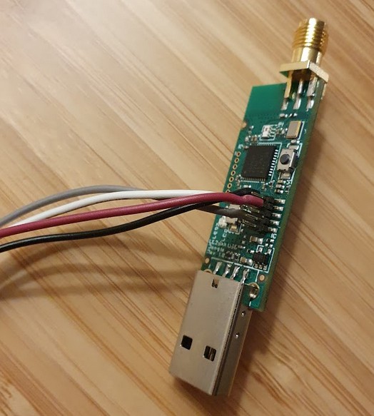
CC2531 is a single chip microcontroller 8051 with a radio periphery transceiver for Zigbee / IEEE 802.15.4 and an USB interface, produced by Texas Instruments. Since it has a programming port, you can upload/install a custom firmware which acts as a zigbee. When you buy this device it’s is shipped preprogrammed as ‘protocol sniffer’. However in my case, I have this device but with the zigbee2mqtt firmware. So, I will rollback to the original Texas instruments firmware. As also, I don’t have the CC debuger, I will use the arduino option with version ModeMCU.
let’s get to work :)
Flashing the CC2531 stick with NodeMCU
The firmware can be donwload in the PACKET-SNIFFER version 1 not the 2. link As the sniffer firmware is only available in the windows installer, the first step is to extact the hex file. For that, it would require 7zip. You can install depending your distro p7zip-full or p7zip-plugins package.
unzip swrc045z.zip -d PACKET-SNIFFER
The installer containt differents files, but the important for us it’s include in the folder “bin/general/firmware/”. Extrar the CC2531 sniffer intel hex firmware.
7z e PACKET-SNIFFER/Setup_SmartRF_Packet_Sniffer_2.18.0.exe bin/general/firmware/sniffer_fw_cc2531.hex
To upload this information with the Convert the hex file to a bin file - under linux the command
objcopy --gap-fill 0xFF --pad-to 0x040000 -I ihex sniffer_fw_cc2531.hex -O binary sniffer_fw_cc2531.bin
Prepare NodeMCU (ESP8266) Board
To flash the NodeMCU with the “Arduino\CCLoader\CCLoader.ino” from the following links using your favorite Arduino flashing tool.
Edit lines 86-90 to change pins for connecting the Zigbee module:
// Debug control pins & the indicate LED
int DD = 14; //GPIO14=D5 on NodeMCU/WeMos D1 Mini
int DC = 4; //GPIO4=D2 on NodeMCU/WeMos D1 Mini
int RESET = 5; //GPIO5=D1 on NodeMCU/WeMos D1 Mini
int LED = 2; //GPIO2=D4 and the Blue LED on the WeMos D1 Mini and the ESP-12E module on the NodeMCU, or can use GPIO16=D0 for the other Blue LED on NodeMCU
Compile and upload.
Wiring the ModeMCU to the CC2531 device.
In your board you need to identify these pins to intend to flash:
| Pin Name | Pins | ModeMCU |
|---|---|---|
| Debug Data | Pin 4 | D5/GPIO14 |
| Debug Clock | Pin 3 | D2/GPIO4 |
| Reset | Pin 7 | D1/GPIO5 |
| GND | Pin 1 | G |
Connect the ModeMCU pins and Zigbee module CC2531 pins according to the table.

Compile the CCLoader
Compile the CCLoader to flash the CC2531 with the “CCLoader/SourceCode/Linux/” from the following links.
Compile the C file.
gcc main.c -o CCLoader
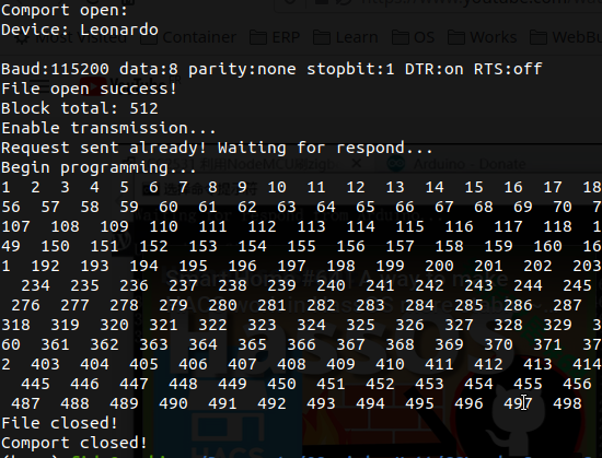
And to finish, execute this command to start the flashing process
sudo ./CCLoader [COM port path] sniffer_fw_cc2531.bin 0
If the flashing not works, please try using 1 instead of 0 in the last parameter.

Thank you for the initial photo.
Photo by Clint Patterson on Unsplash